Welding Works completed a major architectural ornamentation project installed on the Great Platte River Road Archway Monument. Stretching across Interstate 80 in Kearney, Nebraska, this 309-foot-long archway honors the pioneers who traveled west, 160 years ago, on the Great Platte River Road, whose path the Interstate now follows.
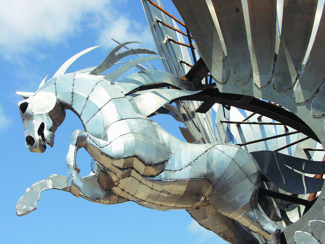
Welding Works’ role in this ambitious undertaking was the fabrication of the symbolic exterior ornamentation for the structure. Designed by Kent Bloomer, the ornamentation includes two sets of 25-foot-high aluminum wings which are mounted atop the north and south towers of the Archway. Wings were chosen by Bloomer to symbolize movement, transportation and communication. An aluminum horse leaps out of one set of wings, representing the Pony Express. All aluminum plate ornaments were cleaned and left in their natural finish. Supporting the ornaments are approximately six tons of sandblasted and painted structural steel, also fabricated by Welding Works.
In addition, Welding Works completed 370 feet of 14-foot-tall aluminum pipe and plate trellis, also designed by Bloomer, and sixteen galvanized steel stanchions that support the trellis sections. The trellis stretches across the top of the Archway in a braided wave style, evoking the feeling of the Platte River. In all, approximately 12 tons of fabricated aluminum plate and pipe were used in the project. The ornaments were fabricated in pieces as large as possible to expedite final on-site assembly and attachment to the Archway, which was designed by architects Peter H. Dominick, Jr., FAIA, and Robert E. Fitzgerald of Urban Design Group, Inc., Denver, Colorado.
Welding Works negotiated the contract for the work with Kent Bloomer and originally developed the scope of the work. During the engineering and design phase of the project, the design of the wings was the first and most important step. However, each pair of wings needed an independent structure behind it and inside it for support and to allow the interfacing of the artwork to itself and the steel structure on the building. The design of these structures was the responsibility of Doug Rutledge, Project Engineer at K L & A (structural engineer for the project), who supplied rough sketches of the support structure. As complete as they were, there were countless challenges facing Welding Works as they sought to marry the artwork to the structure. Communication between Welding Works and the design engineers was ongoing, and the design engineers also made several on-site visits to Welding Works.
The welding for the project was done exclusively with the GMAW process. Welding Works certified procedures, as well as eight welders, to AWS standards for 5052-H32 and 6061-T6 aluminum material. The filler wire was 5/64″ diameter E-4043. The shielding gas was straight argon. The material varied from .090 thick sheet to 1/2″ thick plate, with the majority being .190 and 1/2″ thick. Welding Works used Miller power sources in a variety of output potentials with Miller XR-30 wire feeders. These state-of-the-art feeders allowed Welding Works to feed the 5/64″ E-4043 wire, which is very soft, over a distance of 30 feet. This was essential for the job, since the varied shapes and sizes of the artwork were so dissimilar. Some of the pieces were 12 feet by 26 feet, and at times welders were working 30 feet in the air. The vast majority of the welds were fillets in the size range of 3/16″ to 1/4″.
Cutting was accomplished by conventional band saw for the structural shapes (beams, angles, structural tubing, etc.). The plate shapes, which comprised the majority of the foliage, were cut on an AIRCO optic-eye burning machine. This machine has the capacity of cutting six feet wide by 16 feet long sections. Welding Works retrofitted the cutting machine with a Thermal Dynamics STAK-PAC with two power modules and a machine torch. This allowed the company to cut 1″ thick plate, which was the thickest section on the project. Welding Works added a C&G height sensor for automated cutting. The shapes were taken from the eighth scale and quarter scale models and blown up to full-scale flat patterns. These patterns were then made into a black-on-white template, so that the optic-eye tracer could follow the shape. An operator was thus able to cut a multitude of varied shapes with speed and accuracy. There were over 1,000 different shapes in the project.
Forming presented a considerable challenge. The models in eighth or quarter scale were the only source of information regarding how much the elements were to be formed. Bloomer’s studio scaled the models and developed rolling and forming templates for Welding Works to use. A trial and error method was generally employed in arriving at the finished look of each shape. Once the shape was developed, Welding Works used a press brake, as well as two rolling machines. The horse was the most time-consuming element of the sculpture, due to the many pieces requiring hand forming. There are over 400 pieces on the skin alone, and another 300 pieces were used to fabricate the body of the horse.
In order to ensure the artwork’s fit on the Archway, and in order to develop the struts that hold the artwork, full-scale mock-ups were required for both the north and south towers of the building. Welding Works employed two types of mock-ups. The data to place the foliage were developed from a survey of the building that was taken on the roof in Nebraska. The artwork was laid out and supported in its proper relationship to the building and to itself. Struts were then developed to hold all the foliage. To further ensure that the artwork would fit when it reached Nebraska, a complete vertical mock-up of all the assemblies was performed. The survey was used to develop pedestals that represented the building pedestals. The steel support system was erected in Welding Works’ yard, and then all the artwork was hung on the steel in full scale. Each end was also mocked-up full-scale, with all the elements placed in their proper relationship. Struts were developed for all of these pieces as well.
This simulation of the existing conditions at the site and test-assembly were especially important. Due to the complexity and the irregular shapes, Welding Works had to make sure that all assemblies fit together and would go on without any interference. Structural engineers were also able to clarify many items that were impossible to calculate on paper. The test-assembly also enabled Kent Bloomer to view the completed ornaments and determine if the artistic criteria had been met. In short, it gave all parties concerned a sense of security, knowing that any problems would be worked out at Welding Works before shipment.
After test-assembly at Welding Works, the ornamentation was delivered to Nebraska. Five truckloads, most overwidth, transported the project to the site. The Great Platte River Road Archway Monument welcomes visitors to two levels of interactive exhibits, housed within the Archway, which help make the Wells Fargo Stagecoach and the Pony Express “come alive”.
Oak Bridge Re-creation
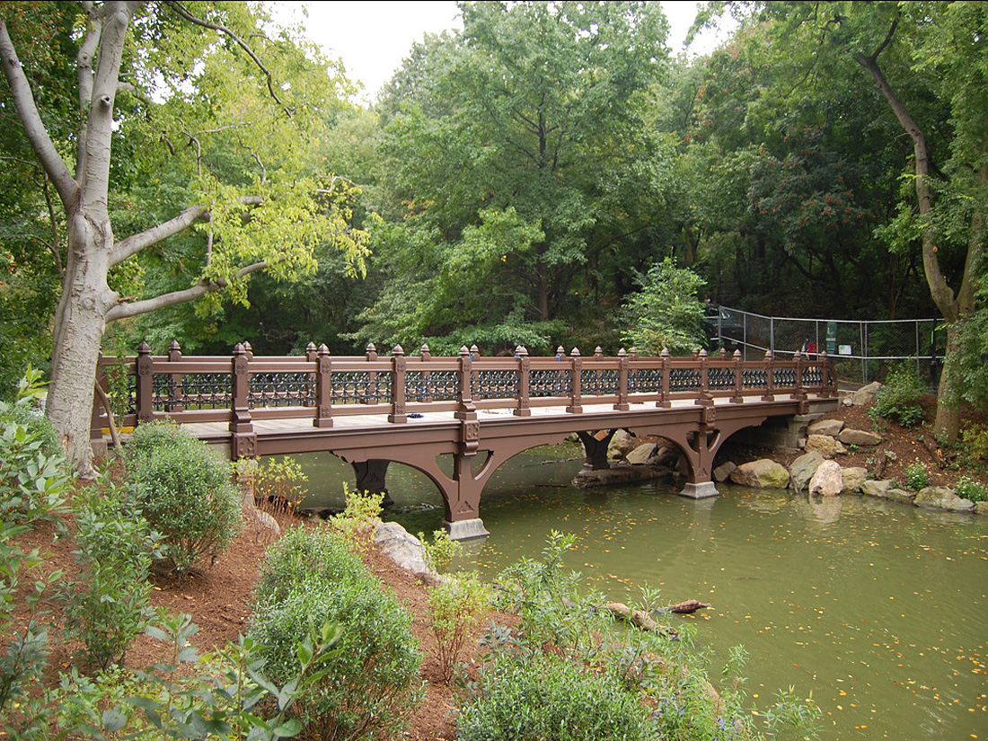
The Central Park Conservancy made the decision to replace an existing utilitarian footbridge with a replication of the Oak Bridge, which was first built in 1860 at the same site. The original design of the 75-feet-long, 13-feet-wide bridge would be approximated using more modern, and durable, materials.
The Welding Works team provided a whole package of services for this project, from a preliminary review of the plans and purchasing of materials to problem-solving and installation. Some highlights:
Our team converted the architect’s plans into makeable parts that would last well into the future. Our fabrication work encompassed decorative cast aluminum end posts; decorative cast and welded aluminum balustrade infill panels; decorative cast aluminum balustrade posts; and decorative cast aluminum medallions. Our goal was to ensure that all individual parts and sections would fit together properly.
Welding Works worked closely with our pattern maker to generate patterns for the large number of castings that the project required. This was particularly challenging because many of the castings would function as cosmetic cladding to cover I-beams, and each cover had to have a left and right pattern that fit together seamlessly.
We helped to create a fastening system that resembled the original one. Since the new bridge had to look like it was built in the 19th century, metal fasteners and brackets could not be visible. The hidden fastener system that was devised included cast aluminum hanging brackets.
A mock-up was assembled at our Madison, CT facility. One complete section of the bridge, consisting of a steel I-beam and its corresponding aluminum covers and grills, was completely put together for evaluation.
All aluminum castings were powder coated before the bridge was assembled. A brown coating with a bit of texture was used to simulate wood. The decorative panels between the vertical posts were coated with black to resemble wrought iron.
All handrails, castings and customer-supplied wood decking were assembled on-site. Once assembly began, field conditions required some creative fitting of sections of the bridge. The aluminum material had some degree of “give,” allowing these adjustments while maintaining the integrity of the structure.
Re-creation of 1860s Central Park Fence
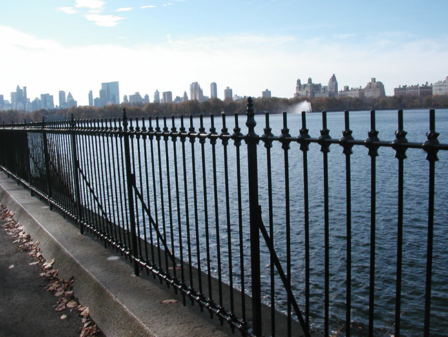
The result of a Connecticut company’s “Yankee Ingenuity” is now being appreciated by the thousands of people who visit and use New York City’s Central Park every day. Welding Works of Madison, Connecticut recently completed a brand-new fence to replicate the one that surrounded the Central Park Reservoir from 1862 until 1926. The original ornamental fence was unique in design and construction, unlike any fencing normally being produced today. Welding Works was challenged to “think outside of the box” to deal with the complexities of the project. They used reverse engineering and investigated technologies used in the past to develop a workable design, fabrication and installation plan.
The American Fence Association recently recognized this Welding Works project with the organization’s Fence Project of the Year Award. Welding Works received this honor during FENCETECH’04, the Association’s annual convention and trade exhibition, held in Orlando, Florida from February 25-27, 2004. According to the American Fence Association, “The Fence Project of the Year Award is bestowed upon the company that has demonstrated unique workmanship and exemplary knowledge of fence installation.”
The original ornamental fence was unique in design and construction – its finials and ornamental unions were cast around, not fastened to, its pickets and rails. The only mechanical fasteners used were to join the panels to the posts. The replica would be installed on existing coping stone and would measure approximately 8,150 feet in length and 48 inches high (an adequate height, since the Reservoir is no longer used to supply drinking water).
Since this project had to be true to the original 1862 fence, no fasteners, pins or welds could be visible. The new panels were to be of welded construction, and this posed one of the project’s biggest challenges – developing the manufacturing methods to cast around the weldment in a cost-effective, productive manner. To ensure that the mold would fit snug at each union for dead-on castings, the first step was to create precise assembly fixtures for accuracy. The weldments needed to be ±.15 inches to guarantee that the castings would be correct. The weld fixture held the steel posts in place with pneumatic clamps and enabled two workers to weld at the same time.
Meanwhile, Welding Works also formulated a plan to ensure that the castings would match the original fence and worked hand-in-hand with mold designer Jim Case to design a unique 3-piece mold. This mold would not only ensure that sufficient iron got into the mold and filled all the gaps, but it could also be removed without damaging the casting. Since the iron would solidify almost instantly, it was a challenge to get good, tight, full castings. Case created a sandcap pouring basin that allowed extra metal to feed the mold to compensate for shrinkage during cooling.
Ultimately, over 1,400 cast iron molds were used to create 19 panel mold assemblies and 16 post mold assemblies. Before casting the unions on the panels, comprehensive load tests were performed to ensure that the fence would comply with the latest code of 200 pounds of force. It was determined that the posts could support over 900 pounds of pressure with no permanent deflection.
Welding Works has calculated that they fabricated 1,535 fence panels, each 5 feet 6 inches long, with 26 castings per panel. Each panel was joined by a post, for a total of 1,538 posts, each with 2 castings. In total, the project encompassed more than 43,000 castings.
All installation procedures were developed and tested at Welding Works before attempting installation on site. Welding Works’ Walt Camp explained, “Generally, on a field installation, you would have the opportunity to problem-solve and perfect the procedure as you go along. With such a tight schedule, we had to perfect the installation methods beforehand.”
The fence was completed and dedicated in December of 2003. It has been called the “single most dramatic change to the Park in 100 years.” It provides an unobstructed view of the Reservoir, as well as of the Manhattan skyline. There have been virtually no negative comments about the project. Christopher Nolan, the Central Park Conservancy’s Vice President for Capital Improvements, reports, “The fence has been very well-received. It restores the historic aesthetic of the Reservoir and changes people’s entire perception of Central Park.”
For more information, please contact: Welding Works, 32 New Road, Madison, CT 06443, phone: 203-245-2731, fax: 203-245-0823, email: sales@WeldingWorks.com.
The Harold Washington Library Center: Aluminum Roof Ornaments
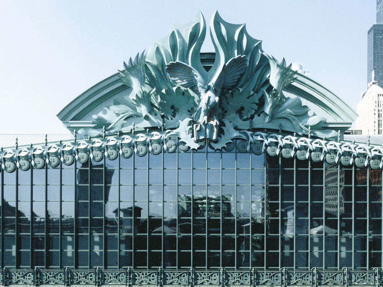
For over a year, Welding Works was involved in an immense project: fabricating seven aluminum ornamental structures for Chicago’s Harold Washington Library Center. We fabricated over 90 individual ornaments, designed by Kent Bloomer, which we then assembled into 7 major structures that have just been installed at the Library’s 4 corners and 3 entrances. These structures, which measure as wide as 75 feet and as tall as 40 feet, each consist of an aluminum support frame to which the individual assemblies are attached. We estimate that over 1 million welds were required to complete the project. In all, 100 tons of sheet, plate and structural aluminum were used. Aluminum was chosen for its strength and durability, as well as its comparatively light weight. 80,000 pounds of galvanized structural steel were also required to provide support for the ornamental structures.
Architect Thomas Beeby, of Hammond Beeby and Babka, the firm that designed the Library, developed the concept and architectural scheme of the ornaments for the building. His ideas were interpreted by sculptor/ornamenter Kent Bloomer and sculptor Raymond Kaskey. Bloomer, Professor of Architecture at Yale University, designed the ornamental foliage. He says, “The botanical ornaments for the Chicago Library are descended from the ancient classical tradition in which significant features found within or derived from nature … are placed in prominent locations upon an important building to symbolize the forces of life and eternity.”
The foliated ornaments are composed of winged leaves and curling foliage. Kent Bloomer and his assistant William Jelley made wood and foam models of the ornaments that were used for designing, quoting, engineering and fabrication. From these, we developed full-size patterns that were used to cut the intricate shapes from sheet and plate up to 1″ thick. Close to 1,000 different shapes were produced in this manner.
Forming proved to be one of the most demanding aspects of the project. A trial and error method was generally employed in arriving at the finished look of each shape. Once the shape was developed, a press brake and 2 rolling machines were used for forming. Considerable hand work was also needed to bring the elements into their final configurations.
While 2 of the major structures include large seed pods at their centers, the other five feature owls, which serve as symbols of wisdom. A 20 foot high horned owl is nestled in the foliage above the main entrance, and 12 foot high barn owls are part of the ornamentation installed at the four corners of the building. All of the owls were designed by Raymond Kaskey of Washington, DC. The owl sculptures were sandcast in segments in Germany, then returned to the United States, where Welding Works welded together the 40 to 50 separate pieces that comprise each figure.
Welding Works test-assembled each major structure at our facilities to ensure that all assemblies fit together properly and that all artistic criteria were satisfied. All unanticipated problems were solved by structural engineers, and an erection sequence to be used at the Chicago site was developed.
In all, 35 tractor-trailer trucks were used to move the partially-disassembled structures from Connecticut to Chicago, 900 miles away. Once they reached Chicago, the ornaments were painted green to simulate weathered copper. Since installation required the closing off of city streets, most of this work was done on weekends only, to avoid impeding traffic.
In the past, almost all of our work has been on industrial jobs. However, this project gave Welding Works the chance to prove our skills in crafting architectural ornamentation.
The work performed by Welding Works for this project has since won two major awards. The first was a 1995 award for outstanding metal craftsmanship in an international competition sponsored by the National Ornamental & Miscellaneous Metals Association (NOMMA). The second recognition came from the Structural Engineers Association of Illinois, which gave the ornamentation project an Award of Merit for its contribution to the state of the art of structural engineering.


